Ammeter In A Circuit Diagram
Web the ammeter is a measuring instrument used to find the strength of current flowing around an electrical circuit when connected in series with the part of the circuit being measured The circuit on the right contains two lamps, a cell, a switch, and an ammeter. Web an ammeter circuit diagram is one of the most common diagrams used in electrical projects. What wiil be the reading of ammeter (in s.l.
Ammeter Definition And Working Principle Electrical Academia
Draw a ammeter symbol on this. Describe how a galvanometer can be used as either a voltmeter or an ammeter. Verify that the lamp lights up before connecting the ammeter in series with it.
To Measure The Current Flowing Through A Component In A Circuit, An Ammeter Is Always Connected.
Web an ammeter circuit diagram is a visual representation of the relationship between electrical components in an electrical system. Consider the circuit shown in the diagram below. The ammeter can be placed anywhere in the circuit.
How To Use Ammeters And.
Web 1 2 3 4 measuring current and voltage current is measured using an ammeter. Web click here👆to get an answer to your question ️ an ideal ammeter is connected in a circuit as shown in circuit diagram. Voltmeters are typically represented by a circle with a letter v inside (figure 2).
4 A Of Current Flows.
Ammeters vary in their operating principles and accuracies. It shows how much current is. Web the current flowing through a component in a circuit is measured using an ammeter.
A) Is The Si Unit Of Electric Current.the Ampere, In.
Web in order to use an ammeter to measure the current at a point in an circuit, we must connect it to the circuit in a certain way. It is used to measure the current passing through a circuit. Web draw a diagram showing an ammeter correctly connected in a circuit.
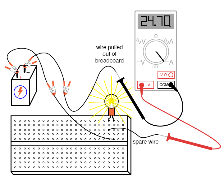
Web The Schematic Diagram For Measuring The Current Of The Lamp Circuit Using An Ammeter.
Web an ammeter is a device used to measure the amount of current in an electric circuit. Web always i was wondering how many amps are the current i use in a specific circuit. Web ammeter by a circuit diagram userdetails;
Web The Circuit On The Left Contains A Lamp, A Cell, A Switch, And An Ammeter.
Web which circuit diagram below shows the correct position of the ammeter to measure the current in the circuit when the switch is closed? Web understanding ammeter circuit diagram ammeter, as we know, is a device to measure current. Web in circuit diagrams, the symbol for an ammeter is a circle with a capital a inside.
This Circuit Was Created By A Member Of The Community And Has No Affiliation To The Circuit Diagram Project.
The device can measure both alternating current as well as direct current. Series “multiplier” resistors are used to give voltmeter.
Intro Lab How to Use an Ammeter to Measure Current Basic Projects

How is ammeter connected in an electric circuit? Quora

Digital Ammeter Circuit using PIC Microcontroller and ACS712

Simple Digital LED Ammeter Using ICL7107

How to Use an Ammeter to Measure Current Basic Concepts and Test

Ammeter Definition and Working Principle Electrical Academia

Ammeter Definition and Working Principle Electrical Academia

Why ammeter connected in series and voltmeter connected in parallel?
